| 12.11. Warp | ||
|---|---|---|
 |
12. Map Filters |  |
| 12.11. Warp | ||
|---|---|---|
| |
12. Map Filters | |
This filter displaces pixels of active layer or selection according to the grey levels of a Displacement map. Pixels are displaced according to the gradient slope in the displacement map. Pixels corresponding to solid areas are not displaced; the higher the slope, the higher the displacement.
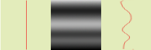
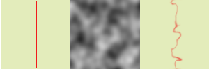
Figure 16.267. From left to right: original image, displace map, displaced image
Solid areas of displacement map lead to no displacement. Abrupt transitions give an important displacement. A linear gradient gives a regular displacement. Displacement direction is perpendicular to gradient direction (angle = 90°).
Figure 16.269. With a complex gradient:
And a complex gradient, such as the Solid Noise filter can create, gives a swirl effect.
This filter offers the possibility of masking a part of the image to protect it against filter action.
This filter is found in the image window menu under ? ? . This filter has no Preview.
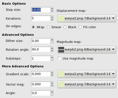
Basic Options
“Step” is displacement distance for every filter iteration. A 10 value is necessary to get a one pixel displacement. This value can be negative to invert displacement direction.
Iteration is the number of repetitions of effect when applying filter.
Because of displacement, a part of pixels are driven over the borders of layer or selection, and, on the opposite side, pixels places are emptying. Four following options allow you to fix this issue:
Warp (default): What goes out on one side is going into the opposite side.
Smear: Emptying places are filled with a spreading of the neighbouring image line.
Black : Emptying places are filled with black color.
FG Color : Emptying places are filled with the Foreground color of the color area in Toolbox.
To be listed in this drop-down list, the displacement map, which is a grey-scaled image, must be present on your screen when you call filter and must have the same size as the original image.
Advanced Options
Once all pixels displaced, this option scatters them randomly, giving grain to the image. The higher this value (0.00-100.00), the thinner the grain.
This option sets displacement angle of pixels according to the slope direction of gradient. Previous examples have been created with a vertical gradient and a 90° angle: so, pixels were displaced horizontally and nothing went out of the image borders. Here is an example with a 10° angle and 6 iterations:
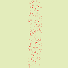
Figure 16.272. With a 10° angle and 6 iterations:
Displacement is made according to a 10° angle against vertical. Pixels going out the lower border on every iteration are going into through the upper border (Wrap option checked), giving a dotted line.
In addition to displacement map, you can add a Magnitude Map. This map is also a grey-scaled image, with the same size as the source image and which must be present on your screen when you call filter. This map gives more or less strength to filter on some parts of the image, according to the grey levels of this magnitude map. Image areas corresponding to white parts of this map will undergo all the strength of filter. Image areas corresponding to black parts of the map will be spared by filter. Intermediate grey levels will lessen filter action on corresponding areas of the image. Use magnitude map must be checked for that.
Figure 16.273. Magnitude Map example:
From left to right: original image, displacement map, magnitude map, after applying “Warp” filter. You can see that the black areas of magnitude map prevent filter to take action.
More Advanced Options
These extra options let you add two new maps, a gradient map and/or a vector map.
![[Note]](images/note.png)
|
Note |
|---|---|
|
To test these options alone, you must use a map with a solid color for all the other maps. |
The gradient map is also a grayscaled map. Here, the displacement of pixels depends on the direction of grayscale transitions. The Gradient scale option lets you set how much the grayscale variations will influence the displacement of pixels. On every iteration, the filter works of the whole image, not only on the red object: this explains burredness.
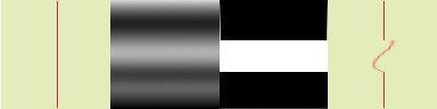
Figure 16.274. Gradient map example

From left to right: original image, displacement map, after applying “Warp” filter with a Gradient Scale map. Gradient is oblique, from top left to right bottom. The part of the image corresponding to the gradient is moved obliquely, 90° rotated (Rotation Angle 90° in Advanced options).
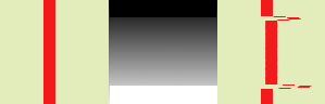
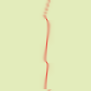
Figure 16.275. Vector map example

From left to right: original image, displacement map, after applying “Warp” filter with a Vector map. Gradient is vertical, from top to bottom. Vector angle is 45°. The image is moved obliquely, 45° to the top left corner. The image is blurred because every iteration works on the whole image, and not only on the red bar.
With this map, the displacement depends on the angle you set in the Angle text box. 0° is upwards. Angles go counter-clockwise. The Vector Magnitude determines by how many pixels the image will move on every iteration.